AERIAL SURVEY OF FIX ASSETS IN THE RIGHT-OF WAYHuug HAASNOOT, The NetherlandsKey words: LiDAR, Corridor Mapping, 3D-geometry, Ortho-rectified, geo-referenced video images, Automatic Filtering Routines, Synchronised video imagery 1. AbstractHigh density airborne LiDAR, being an innovation in remote sensing techniques, has now taken away the barriers of the traditional survey techniques. Especially for long corridors like roads, railway and electricity lines, laser alitimetry provides a new survey method to collect remotely sensed data in a quick way. Particularly the LiDAR systems which operate with the latest technology at low altitude (50-70 m) and low speed (50 km/hour) present a professional survey tool that can compete with traditional survey methods as it is precise (5-8cm absolute X,Y,Z accuracy), reliable, fast (150 km per day) and cost-effective. The advantages of aerial surveys are twofold: obviously the safety aspect is very important as surveyors are not required to physically occupy the survey area and secondly for the transportation industries it is essential that the survey will not interrupt the schedule of trains / road transport. Further aerial surveys are not compromising the environmental conditions, nor any permits are required to have access to every property. Fugro, a multinational on the Dutch stockmarket with more than 200 offices worldwide, has developed the Fast Laser Imaging and Mapping Airborne Platform (FLI-MAP®) system in 1996, fully based on the reason that long corridors do not lend themselves well to conventional land survey techniques. Since 1996 this new high-detail aerial survey method has been used successfully world-wide in more than 150 projects. The high point density (10-20 points per m2), high accurate data of the FLI-MAP system enables the surveyor to map all assets along corridor like railway tracks and powerlines to details of signals, tracks, junction boxes, sag of conductor lines, the location and height of existing buildings, etc. This information can also play an important role in the determination of the optimum route for a new line. A dedicated processing package supplies filter algorithms and CAD functionality "on top of" the laser data as well as fully synchronised video imagery, providing additional capabilities to the operator in extracting valuable information from the LiDAR data. This extracted information can easily be incorporated in external specific GIS or CAD software packages. Recently software development has been concentrated on automatic filtering routines and the possibility to generate otho-rectified, geo-referenced images.
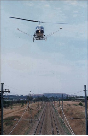
Bell 206 Helicopter with FLI-MAP® system As of August 1999, Fugro-Inpark operates the third FLI-MAP system from the Netherlands to execute projects in the Eastern Hemisphere. During the last 1.5 years projects have been completed in various industries with a variety of endproducts, e.g. detailed Digital Terrain Models with more than 10 points per m2 for flood control in the Netherlands, planning of new roads for the expansion of tourism on French Polynesia, high-accuracy cross-profiles of the Expressway near Kuala Lumpur, planning of noise protection walls for the German railroad, coast line protection survey in Portugal, etc. 2. TECHNICAL INTRODUCTIONThe integration of numerous latest innovations such as the high frequency scanning laser, the solid state Inertial Navigation System, kinematic GPS technology, automatic filter routines and mosaic of digital ortho-rectified video images has provided numerous industries a new survey tool and a near continuous 3D-geometry coverage of terrain features. This, in combination with dedicated software, has resulted in an outstanding tool to inventorise corridors for the railway, pipeline, electricity, and tele-communication industry. Installed on a helicopter, the FLI-MAP system is navigated at a low altitude along the corridor collecting GPS, scanning laser, helicopter attitude, and video information. The helicopter gives the system a unique perspective to efficiently gather sufficient data to determine characteristics such as powerlines attachment points, sag of conductors, signals, junction boxes in the railroad industry and land use to aid in the engineering process without occupying the actual ROW or touching the conductor. FLI-MAP's scanning laser is a custom designed eye safe, reflectorless rangefinder capable of measuring first return ranges from 20 to 200 meters. Every scan has a width of 60 degrees and contains 200 range measurements. Each scan record contains timing, laser attitude, and intensity of the reflection and data verification/error detection information.
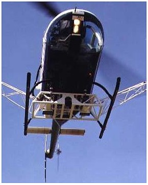
The FLI-MAP helicopter with the two eye-safe lasers Operationally, the laser scans at a rate of 55 times per second and has a coverage width that is 1.15 times the helicopter's altitude above ground level. A military classified Solid State Inertial Navigation System (INS) measures heading, pitch, roll information as well as 3D velocities, maximum 200 times per second. By matching the GPS derived position with the INS data, a position of the laser is determined for every scan. This information, with the scanned ranges, produces the XYZ positions of the laser returns on the terrain along the flight path. FLI-MAP can be configured to operate with two scanning lasers simultaneously. The primary laser is tilted 7 degrees forward to ensure enough reflections will be collected on the front of buildings. To ensure that also the rear of objects are surveyed, the secondary laser is tilted 7 degrees backwards. Two colour S-VHS video cameras, one downward looking and one at 45 degrees forward looking, are collecting digital video images of the survey corridor. In addition to being used to show terrain conditions and identify objects, the S-VHS video can provide captured digital images which can be used in data processing. Flying at 20-225m attitude with a speed of 50-70 km/hr the FLI-MAP system makes between 11,000 to 22,000 range measurements per second, resulting on average to 10-15 points per m². This high point density allows accurate and reliable position and height of all objects in the corridor.
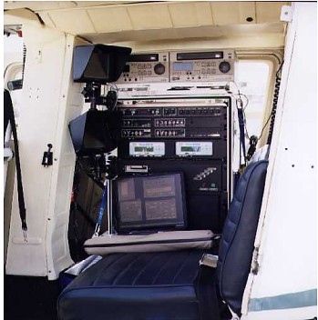
FLI-MAP® equipment inside helicopter Based on those numbers the system collects on average between 1,000,000 and 2,500,000 3D data points per kilometer of Right Of Way. This volume of data can be handled and manipulated by Fugro's FLIP7™ software which allows an operator to easily access the information that is required. This package has been developed for processing airborne LiDAR data and has tools designed to streamline the extraction and formatting of specific information such as conductor clearances, centerline profiles, rails positions, etc. FLIP7 is used in the process of preparing traditional deliverables such as plan and profile sheets and digital input files for engineering design software packages. In addition, the software gives the engineer the ability to confirm measurements or conditions at his or her desktop, without the need to send survey crews into the field. 3. FLI-MAP SURVEY OPERATIONSReconnaissanceFour to five reference locations (every + 20-30 km) are planned each flight session which will guarantee the necessary accuracy, quality control and back-up in case of problems on a base station, assuring that the distance between the helicopter and a base station never exceeds 10-15 km. The reconnaissance survey ensures that the base stations are correctly spaced taking terrain constraints and local conditions, like hazardous surroundings, into account. During the preparation phase also local helicopter companies are visited to check availablility and prices. The FLI-MAP system is worldwide certified by the American Federal Aviation Authorities on 5 different type of helicopters: Bell Jetranger, Bell Longranger McDonnell-Douglas 500, Eurocopter AS350 (A-star) and Eurocopter AS355 (Twinstar). Independent of the country (e.g. South Africa, Portugal, Germany), the mobilization of a helicopter has taken a maximum of half a day. GPS planning software is used to determine the time schedule for the flight sessions. Those survey windows are generated such that at least 6 GPS satellites can be observed at the same time. This is essential for an accurate and reliable positioning of the helicopter and thus the co-ordinates of the laser points. OperationsThe total FLI-MAP system is mobilised on a Bell 206 Jetranger within 4-5 hours. After a project briefing and specific instructions to the pilot, the survey can be started in the afternoon of the first day. Fugro Omnistar® satellite receivers are used to collect standard RTCM-104 differential corrections, which provide a sufficient accuracy for real-time navigation to guide the pilot along predetermined survey flight lines or to waypoints. The pilot and operator can view both the down-looking and forward-looking video on a flat screen colour display, while the operator has a specially designed interface for control and status monitoring of the system during operations. The Fugro crew consists of a Pilot, a System Operator, a Supervisor Field Operations, two Data Processors and a field crew of on average four to man the base stations. An average of two to three flights are completed per day, each lasting + 2-2½ hours. During each repose period for the pilot and operator, the field crew travels approx. 100km to the next reference locations along the corridor. As of autumn 1999 more than 13,000 km has been surveyed in various countries and industries of which below a summary is included:
Quality ControlDaily, the GPS data is downloaded from all base stations and the two GPS receivers on the helicopter. This data is processed into accurate positions of the laser returns and reviewed during night to assure full coverage and required quality. Pre-processing comprises of the following control measurements to check the final quality of the surveyed data:
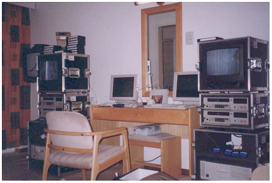
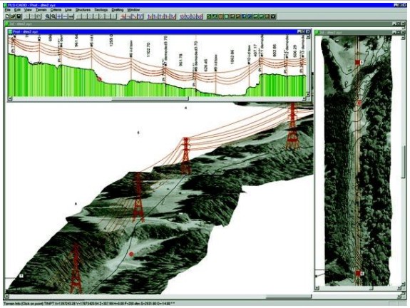
Set-up of computer and video recorders in a hotel room in South Africa during pre-processing operations 4. DATA DELIVERABLES AND ORTHO-RECTIFIED IMAGESGeneralThe FLIP7 software package is used to process the billions of X,Y,Z-points, into various standard endproducts:
FLI-MAP® video capture of forward oblique perspective FLIP7 is a Microsoft Windows NT 4.0 true 32 bit Windows application that merges the GPS position and INS attitude information with the LiDAR sensor data and video imagery. The package provides full CAD (Computer Aided Drafting) capabilities "on top of" the LiDAR data, providing additional intelligence to the CAD drawing. Each layer contains drawing objects, which include points, polylines, and "groups", or collections of points and polylines. Every class of object can have its own user-defined set of unlimited attributes. Each attribute defined can have an unlimited number of pre-defined values. When the user extracts a point on a given layer, and has a user defined flag set, a dialog box appears with a data base entry table to be filled out. The fields have the predefined values available to be selected. A default value for each attribute can also be defined, as well as simply editing the field with a new value. This data base entry scheme greatly increases the reliability of the data captured by reducing simple mistakes like spelling and redundant naming of attributes.
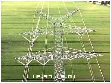
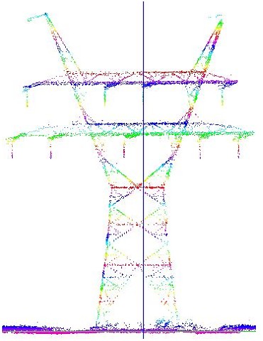
Final CAD drawing of a transmission line Ortho-rectified, geo-referenced video imagesFLIP7, in conjunction with the Windows' application, DVController, controls special time coded MPEG video's allowing the user to co-ordinate the video images with the processed LiDAR data to get a multi-media presentation of the surveyed area. This new development within FLIP7 is capable of capturing frame(s) of the downward video at the desired location The pixels of the captured image are then corrected for position, heading and height and 'fused' with the laser data to present the image as a geo-referenced ortho-rectified image. This provides not only better view for the operator on the video images and thus optimises the recognition of objects and attributes, also it enables the operator to correctly determine the position of small objects as the resolution of the video images is higher than the laser point density. Not only single images can be ortho-rectified this way, the software also offers the possibility to generate automatic seamless mosaics of rectified video images along the line of flight.
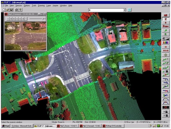
Example of FLI-MAP laser data fused with a mosaic of ortho-rectified, geo-referenced video images Automatic filtering routinesTo enable automatic classification and feature extraction, the FLIP7 Processing Package has been expanded with various filtering routines. The filters can be developed as fairly simple modules for specific tasks (e.g. find ground points, or calculate average height), but the ability of filters to communicate with each other also makes it possible to build complex algorithms. Such filters have already been successfully used to automate the classification of terrain features and, in so doing, have reduced the task of manual classification and interpretation from several weeks to only days. Over 25 filters are currently available, the most important of which include:
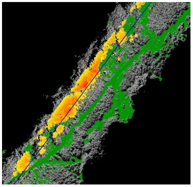
Combination of ground filter (green points) and filter that detects areas of danger close to a power line. Yellow points that identify trees at a safe distance (approx. 10m) change to red when they are within 2-3m of the power line. One result of this is that automatic filtering routines that operate independently of FLIP7 can now be written by third parties. This will be aided by a Visual C++ Filter Wizard to be included in a software development kit. 5. CONCLUSIONMore and more clients realise that the barriers of the traditional techniques for corridor mapping have disappeared now that aerial laser altimetry can provide a unique method to survey long corridors by collecting remotely sensed data in a precise, reliable, cost-effective and quick way without physically occupying the Right Of Ways. The laser imaging and ranging data, integrated with the information from kinematic GPS techniques, INS systems and digital ortho-rectified video images, provide clients a fast, save and cost-efficient alternative for traditional surveys. The accuracy of the advanced LiDAR surveys is comparable to the conventional land survey methods and the qualitative and quantitative nature of the FLI-MAP data has allowed engineers to analyse drainage conditions, measure clearances between overhead power lines, or model any area along the survey corridor.
Cross Profile of Electricity Line BIOGRAPHICAL NOTEHuug Haasnoot has more than 12 years experience in the
survey industry after graduating in 1988 from the Technical University
of Delft, The Netherlands, with a MSc. in Geodesy. CONTACTHuug Haasnoot 15 April 2001 This page is maintained by the FIG Office. Last revised on 15-03-16. |